Click here for the pdf manual of version 3.1 (page below is version 2 and an early iteration of 3.)
Version 3.0 schematics as pdf's:
Desk Unit
Hub
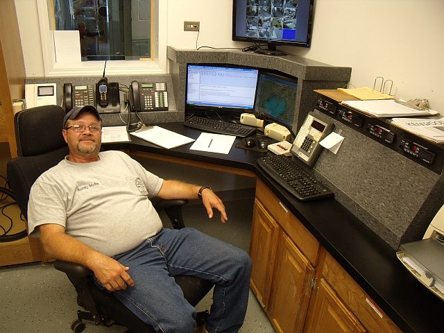
Description below is for Version 1. The police department moved to a new location and the system was replaced by version 3 in early 2016. Use links above for that. Here is a picture of Version 2 (the remainder of the page describes a transistion design between 2 and 3).
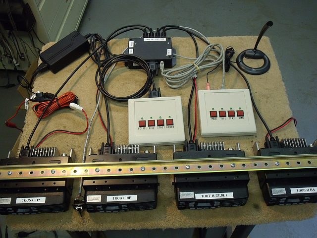
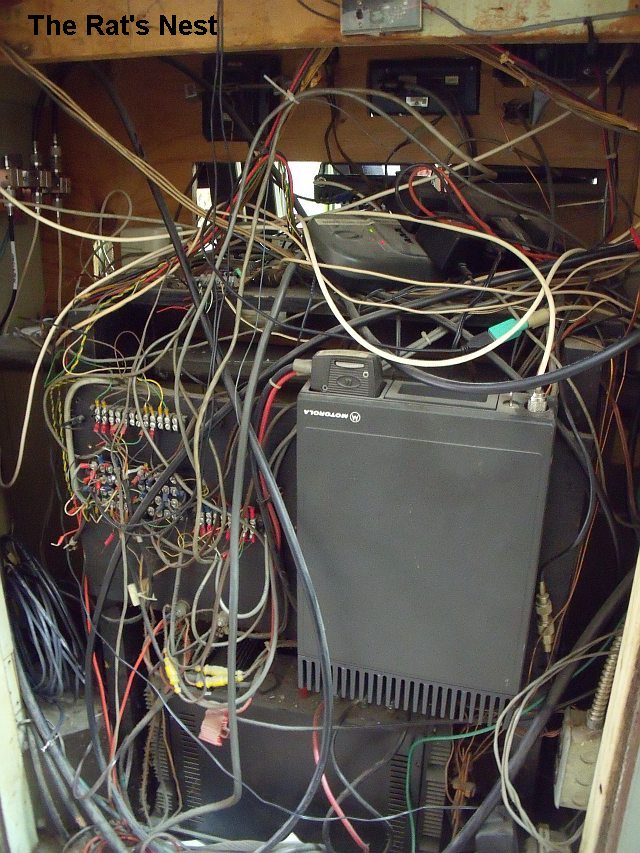
My local police department dispatcher position has migrated from an aging rat's-nest connecting three older radios (all different Motorolas) to four new Kenwoods, all alike. This enables them to go narrowband when that becomes unavoidable, and also moves them from a cramped corner into a new room. I was given the task of mounting the radios into a cabinet built by someone else (with some suggestions from me), and replacing the rat's nest with something a little more organized. They also wanted a second control position for occasional use. Since the radios are in the same room, the radio speakers did not need to be remoted; both positions are able to hear them well. The primary operator, sitting right by the radios, would have easy access for frequency changes, although only the 4th radio would normally be subject to change; the first three are dedicated to Police, Fire, and State Net. So the main needs were for combined PTT points and a mike for each dispatcher, connections to the paging and siren encoders at the primary position, and balanced lines from each radio to a multichannel logging recorder, mixing the transmit and receive audio. The result is shown at right.
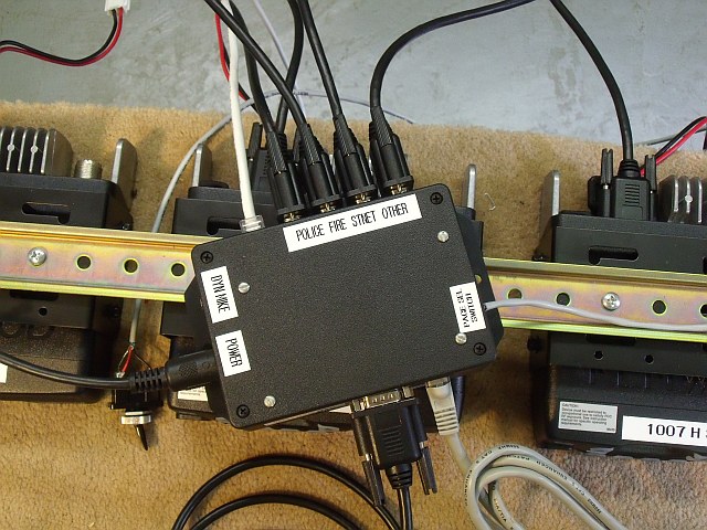
The next photo shows the central logic box. The gooseneck mike for the main position plugs in below the label "DYN MIKE." The secondary position uses a common computer style desk mike (shown in photo 1) that plugs into the desktop box. The main position can also accept the same kind of mike, but they wanted to keep the much more substantial mike they are using. Power is supplied from an IBM brick that I had on hand, which provides ±12v and +5v. The main paging encoder can be switched from radio 2 to radio 1, a safety backup to match the existing arrangement. The weather siren encoder is wired through to radio 4, since it uses a different frequency. This eliminates changing the channel on the fire radio to send those codes, as they did before.
The Kenwoods had to be modified to be compatible with the electret-level mike output. (Kenwoods use a dynamic mike input, and also accept a line-level "data" input: one is too low [5mv], the other too high [.2v pp].) Joining the "data" input with the "TXAFI" input (they go to the same IC pin through different resistors) gives a sensitivity of about .12v pp, which worked well. Unfortunately, Kenwood also does not provide a SQUELCHED receive audio output, so I mounted a 2N7000 mosfet switch in each radio, sent the unsquelched DETO (Detector Out) through a resistor to an available accessory pin, and let the transistor shunt-switch that pin, using the speaker mute line to control the transistor gate. I have years of experience with Motorola radios, which use electret mikes and which do provide squelched Rx audio to the accessory connector. So this system should be actually easier to connect to Motorola radios, as long as they maintain that standard. (addendum: it turns out that DETO is pre-unscramble, so when they "switched over", the recorder was recording scrambled audio, not very useful. So I removed the mosfet switch and took Rx audio from the speaker output. This has three advantages: it is squelched, it is de-emphasized, so it sounds more natural, and it is unscrambled. But it is also subject to the volume control setting, fortunately not normally an issue.)
The PTT desktop units are actually quite simple. The remote unit connects using a standard ethernet patch cord, and simply carries four +5v PTT levels (when the buttons are pushed) and the mike audio. The main PTT unit is connected with a common DB15HD VGA patch cord, as it carries four more +5v lines that serve to give it dominance. That is, if the remote unit has a radio keyed, the main operator can key the same radio and take over; the radio is switched to the main mike audio. Or if the main unit has a radio keyed, the remote cannot break in. Whenever any button is pushed, an LED indicator lights above that button on both units, so both operators can see which radio is in use.
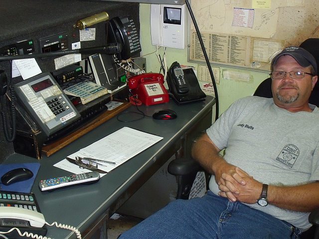
The last photo shows the system in place (on the right). The power supply fits easily inside the cabinet, under the radios. A small fan circulates air for cooling. They had planned to use the blank face area for equipment but instead put it under the window. They have since posted many more notices on the cabinet slope, so it will be a billboard.
In the logic box, the mike audio is combined with the PTT line as is standard for Motorola radios, which is another reason this system is Motorola-compatible. After switching, they are then split back apart for the Kenwoods. To attach a Motorola, just connect to the unsplit line. No significant modification required. As for the logging recorder lines, these are basic op-amp buffers with mixer inputs and balanced outputs (hence the ±12v power), sent out to the recorder on a single CAT5 cable. Unfortunately, the Kenwoods threw me one more time when I found that the "TXAFO" line they provide is tapped off before the data/TXAFI injection point, so it carries only the front-panel mike audio, not the accessory input modulation! Since I wanted to record Tx audio both ways, with the hand mike plugged in and not (as a safety redundancy, should the PTT box go down), I had to provide the mix buffers three inputs: RXAFO, TXAFO, and TXAFI. Since all are trimmable for level, this led to a pile of trimpots (12, to be exact). Fortunately, the VGA cables to the radios could support all this. It seems that many VGA cables short all the VGA grounds together (and of course, most vendors do not tell you if this is true of theirs or not), but as it worked out, I did not have to custom-build the cables for the radios.
The radios are mounted in a line on a bar. The lid of the cabinet can be removed and the four-radio assembly lifted out as one unit without disconnecting them. The cabinet supports the bar at each end and in the center. This rapid-access construction has already proved very helpful.
A new design (click here for user manual and photo of prototype) uses interlock. That is, when a button is keyed on one box, the corresponding LED on the other box(es) lights red, which says "this key is in use and is blocked." The rule here is "First One Wins" (F1W) rather than master/slave. This redesign also makes the boxes identical inside, and they all use ethernet cables. The new method senses the direction of current on the line: if coming into the box (from another) it lights the red and blocks the switch, if going out it lights the green and sends the connected mike audio. By riding mike audio on the keying voltage, only 4 lines are needed to control 4 radios from any number of parallel controllers (plus ground and power, a total of 6 wires). The central logic is then even simpler: all it has to do is key the radio and deliver the modulation, using a single transistor per radio.
Receive audios are sent back to the controller positions on the same control lines, then amplified to speakers or headset at each position. Keying naturally eliminates Rx audio on that line but does not affect the audio coming from other radios on the other lines. It is usual for a dispatch console to have a "selected" speaker and an "all others" speaker. The selected speaker is assigned to the last button keyed, on the assumption that it is the preferred channel. The memory is a simple RS flip-flop for each button, which holds the green LED on dimly after keyup as a reminder of the selected channel.
True static monitor function will be provided by adding 4 small buttons to the control boxes. Press to toggle monitor status (red lights dim to indicate monitor). Reset to hung-up by tapping Tx button. Monitor toggle done by adding an RS flip-flop to each line, in the hub. Low voltage from the monitor switch sets the flipflop, higher voltage from the Tx switch resets it. The flipflop sets the radio to Monitor and sends low voltage back up the line to light the red indicator dimly. The same button, held down, mutes that line. This feature came about since the voltage shift would cause a thump in the headset/speaker, so the earpiece is muted on that channel while its monitor button is held. The transmit key also mutes to stop thump. Since you are then speaking, that also prevents you from hearing yourself in your headset, or getting feedback if using speakers.
The new design is to be powered by single-supply +12v (from the radios in the prototype, but due to features added later, power will come directly from the rack power supply), eliminating the ±12v brick. Balanced output is achieved by 600:600 line transformers. Old tech but reliable, and should endure line surges well, useful if the recorder is remotely located.
The hub can have a bank of switches added for repeater setup: switch one radio to "T" and another to "R", then when R receives, it keys T and sends back out. A second bank of switches would allow crossband repeat: the radio pair can then be assigned T>R and R<T, so whichever one receives first keys the other. Thence could a UHF and VHF radio pair port traffic between bands. This involves enabling the "TOR" (tone operated relay) outputs of the radios and adding just switches and diodes to the hub. This feature will be optional. This system should be available in Simple (transmit-only control boxes), Receive (adds gated headset/speaker driver), Monitor (adds monitor buttons), Receive+Monitor (both), and finally, all the previous can have the repeater setup switches installed, or not. All versions will use the same circuit board, populated differently.
There are now plans to add channel-changing ability, as an option, to the controllers. Four buttons labelled 1-2-3-4 and four LED's, dual-color red-green (yellow when both red and green lit). To set a channel: hold the channel number button you want, and tap the PTT of the radio you want to set. The associated LED will indicate the channel (dark for 1, red 2, green 3, yellow 4). Due to the added parts the PCB will be redesigned to fit a bigger console, to wit, the same one used for the first edition (see photos on this page). This will make a total of 16 channels accessible, 4 simultaneously.
And finally (feature creep, yes) activity indication: the red LED used to indicate Mon/OtherKey can also be driven to flicker when there is audio activity on the line to/from a radio (swamped to bright red on OtherKey, but otherwise visible). Click on the link above for the draft service/user manual, which needs updating for these two features.
Although everything could likely be done mostly in one microprocessor chip, I am aiming for long-term repairability, which means avoiding parts and tools (such as programming interfaces) that may too quickly become hard to find or obsolete. (See Are products owned when bought? at EDN Today)
Created on July 31, 2011; updated November 6, 2013