In September 2009 Nuts and Volts magazine published an article by Ron Newton with the title "ReFuseAble Box," about a settable circuit breaker. Having needed such a tool many times, I decided to build one, but without the microchip or digital display. The following is my article submission to them, which was never acknowledged.
For those who wonder why you might want one of these: If you are working on equipment that has been known to pop its fuse at odd moments, it costs less to pull the fuse and connect this device across the fuseholder. Set it for the fuse value, turn on the equipment, and go to work probing for live faults (there are times that this is the better choice than looking for bad components while the circuit is dead; for example, some parts may cause a short only when hot, and return to normal when off, making them hard to find). That way you don't need to keep a full box of assorted fuses at 50 cents each. Before this, I often ran line-operated equipment in series with an incandescent light bulb, which would burn dim until the malfunction occurred, then it would fully light up, preventing real fireworks inside the equipment. But that still supplies some power after the fault occurs, and it does not supply full power when there is no problem.
You can expand these photos to 640x480 by right-click and View Image. Or just use your browser Zoom. The schematic is a 1291x891 gif, so it can be expanded much more.
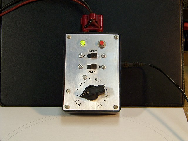
My design uses a simple comparator, a relay driver, and an LED driver. The voltage drop across the sense resistor is compared to the setting of a potentiometer. Trigger current is shown by a dial and knob pointer instead of a digital display. The dial is custom labeled, which is the only "programming" needed. In my design, the bridge rectifier can be switched out of circuit, so that DC under test passes only through the sense resistor. This avoids the 1.2 volt drop in the rectifiers. The switch can be left in the AC position if the drop is not a problem. Two ranges, 1.2 amp and 12 amp, are provided by switching sense resistors. I use .1 and 1Ω instead of .01Ω, which produces a maximum sense voltage of 1.2 volts at 1.2 and 12 amps; no amplifier is needed.
Looking at the schematic, with the linear 10K panel potentiometer at maximum, the 50K trimmer sets the non-inverting comparator input at 1.2 volts. The other comparator input follows the drop across the current sense resistor of .1Ω or 1Ω, selected by SW2, for high and low current range respectively. I was concerned at first about switch contact resistance affecting accuracy, but testing proved that the wire going from the switch to the .1 ohm resistor had greater effect. I had to change it from 18 gauge to 12 (reducing the extra voltage drop from 15 millivolts to about 5mV, at a test current of 2 amps.) The switch added about 2 mV, which is insignificant. I would suggest not moving the switch when a large current is flowing, to avoid sparking the contacts. In tests, the circuit always triggered when the switch was moved. I used both poles of the DPDT switch for the high side (see photo) but didn't bother for the low side. The relay, although quite small, has contacts rated at 12 amps. I scrounged one from a discarded microwave, but Mouser and Digikey carry them quite inexpensively.
When the current exceeds the set threshold, the comparator output goes low, turning on the PNP transistor. I used a "digital" type, which has the base resistor built in, sparing me another external part (Mouser has these for about 15 cents each.) This turns on the relay, breaking the current, and lights up the red half of the two-color LED. It also sends a high back to the comparator inverting input, locking it on. To reset, first remove the excess input current, then press the reset switch to short out the feedback voltage. If the excess current is still there, it will just trigger again as you release the reset. If you want the breaker to stay open while excess current is present even when the reset is pushed, use a normally-closed switch in series with the feedback instead. On reset, the comparator output goes back high (via the 4.7K pullup resistor), and the NPN transistor acts as a follower to drive the green half of the LED. This loads the pullup resistor so lightly that the PNP stays off. The two halves in the LED share a common cathode resistor of 820 ohms.
On AC, the breaker will trigger on a current peak, not on average current. If average is desired, just put a capacitor across the reset switch. This will also slow down the feedback and triggering a little. I haven't tried this, but I would suggest no more than 10µF (1µF or less would probably work).
Power is supplied by a 12-volt-nominal unregulated walwart. I used one marked 12 volts that put out 19 volts unloaded; it was still over 15 volts at the maximum current this circuit draws (about 40 mA triggered; the relay coil draws only 30 mA.) The 78L12 regulator provides the 12 volts power and reference. You could use one of the newer regulated electronic walwarts instead of the 78L12. I didn't want to use the one I have, since it was rated 1 amp, which would be wasted on this circuit. If battery operation is important to you, a 9 volt battery will work if you use a 5 volt regulator and 5 volt relay. Just adjust the trimmer for the correct voltage at the top of the set potentiometer. At 70 mA (a 5 volt relay draws more coil current), the battery won't last long. In the untriggered state, the green LED draws about 10 mA. Important: whatever power you use, it must be isolated from the AC mains, as the fuse point in any device you monitor is likely to be "hot," that is, not at ground. Most walwarts provide isolation, but check it to be sure. At first, I had the box faceplate connected to circuit common, assuming it would be grounded. After realizing that it would sometimes be "hot" and a shock hazard, I isolated it from the circuit.
The bridge rectifier is rated 4 amps, which means it may run rather hot if a current that is too low to trigger the breaker but much higher than the bridge's rating is sent through it for too long. (It is rated 200 amp surge, so a short-term overload is no problem.) Keep this in mind if setting for more than 4 amps. This is another reason for the bridge bypass switch. A 25-amp bridge is quite large. Looking at the specsheet for the comparator, I believe the bridge may actually be unnecessary. Just put a small diode across the reset switch, anode to ground, to protect the comparator from excessive reverse input. Of course, the circuit would only keep watch on half the AC cycle that way, which may occasionally be a drawback.
None of the resistor values are all that critical, except for the sense resistors, which need to be accurate. [Actually you can custom-calibrate the dial for any shunt resistance within reason: the drop being sensed must not be too low or too high. For example, with a .2Ω shunt, set the trimmer for 2.4v at maximum dial. Or accept a maximum trip current of 6 amps, marking the dial accordingly.] The 820Ω was selected for pleasing brightness, the 68K was selected for a reasonable range for the 50K trimmer, the pullup and feedback resistors (both 4.7K) could vary from 2.7K to 6.8K, and the sense-to-input resistor (1K) could be anything from 470 to 22K (or more, since the comparator has high input impedance). With the values shown, the voltage on the input is about 2 volts when triggered. If you vary the feedback and input resistors, take care to keep the lock-on voltage at the input above 1.2 volts. The .1Ω sense resistor needs to be 15 watt rated (12 amps x 1.2 volts = 14.4 watts); I had the 25 watt piece shown, and it fit just right. If you use scrounged used parts like I did, it's a good idea to check them first. My proud first test run failed, and there ensued a little panic until I discovered that the 1Ω resistor was bad.
First, with the internal trimmer, set the voltage at the set-pot top to 1.2 volts. Put the knob onto the pot shaft pointing straight up at mid-sweep. Then metering the pot wiper with a DVM, turn the pot to 1.0 volts and mark the face plate or dial with a dot. This is your 1.0 and 10 amp point. Then put in a test current using a variable power supply and limiting resistor of adequate rating, and confirm that it triggers as current reaches exactly 1.0 amps. I had to readjust the wiper voltage to 1.08 volts, and remarked the dial (alcohol on a Q-tip erases Sharpie marks). To mark the other points, multiply this voltage by .9, .8, .7, etc and turn the knob to the resulting voltages and mark the dial for each one. (For example, 1.08 x .9 = .972.) When done, I tested each point with currents and found excellent accuracy. Then I pricked the faceplate at each dot and erased the ink, then printed out “.1 .2 .3” etc on a label machine (using black-on-clear tape) and, cutting the numbers apart, put the dot directly over the prick (see photo.) (You might prefer “1. 2. 3.” etc) You could get fancy and design a printed dial face on your computer, but since the pot is not likely to be perfectly linear, it wouldn't be as accurate.
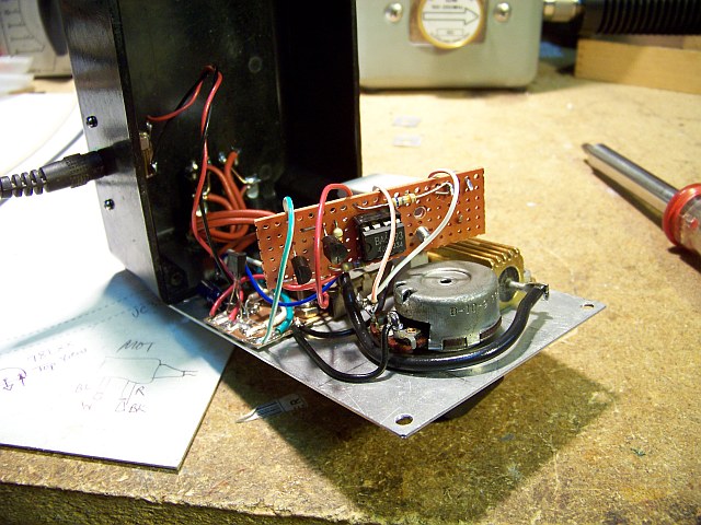
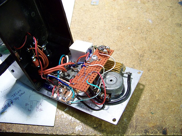
I began construction by assembling the face panel first, and found that many of the connections could be made there (as flying connections) instead of on the circuit board as originally planned. To connect the LED's I used a small piece of plain copperclad and scored out a few square pads on it with a razor knife (see photo). Then I decided to mount the regulator and LED cathode resistor there also. For the main board I used a scrap of unclad perf board and mounted it above the 25 watt resistor on a standoff post (see photo). Pad-per-hole clad board would be better, for stiffer part mounting, but I didn't want to cut my nice pieces down, and I had the scrap of unclad handy. You might prefer to put more of the parts on a bigger board. This is an example of design-as-you-go, not always a good idea, but it worked this time. Obviously a remake would benefit from better construction.
Miscellaneous notes: the relay is mounted with double-sided foam tape, plus one leg is soldered directly to the 25 watt resistor. The LED lens was not designed for a thin metal panel, so I cut and punched two small pieces of aluminum; stacked, these gave enough thickness to hold the lens well. You could just glue the LED directly into a hole. The PBL405 flat-pack inline bridge rectifier is sticky-taped under the input jacks.
Cost of construction: $0, since I had everything from decades of scrounging. If you use all-new parts you might exceed $50, if you pay full price. A note about the box: finding a Mouser equivalent proved impossible; strangely, neither Mouser nor Digikey seem to carry any plastic boxes with metal covers. Their online parameter-search methods leave a LOT to be desired, as truly essential characteristics (such as price and faceplate material) are not among the parameters listed, while obscure (even rather useless) parameters intrude on the search. You may prefer a plastic face, but this will affect the labeling method.
Parts list: (all part numbers are Mouser unless otherwise noted)
Created on ... August 05, 2011
Another successful home project: Electronic wart removal